 |
|
It was two weeks to the WCRG, and one week before the Los Alamos workshop. Having never done a line-following bot, I figured I had enough time to pull it off for the WCRG. Ha! Right!
Actually, I almost pulled it off. I was down to just the programming when I arrived on Dave & Cheryl's door step in Calgary.
|
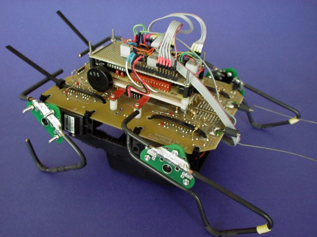
In the end, I flipped the dip switches on the bot to put it back to BEAM mode for the Walker Triathalon, which it won to my suprise...I thought Gnat, my two motor walker would do much better at the WCRG.
|
|
|
|
|
|
With abit of tweaking, I could finally see that I was heading in the right direction.
|
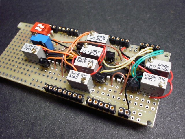
The reason I chose to use this particular circuit was because I had all the parts except the 2N4403 transistors, I used 2N3906's instead. The transistors lined up with the LM324 pin-for-pin too, which was nice.
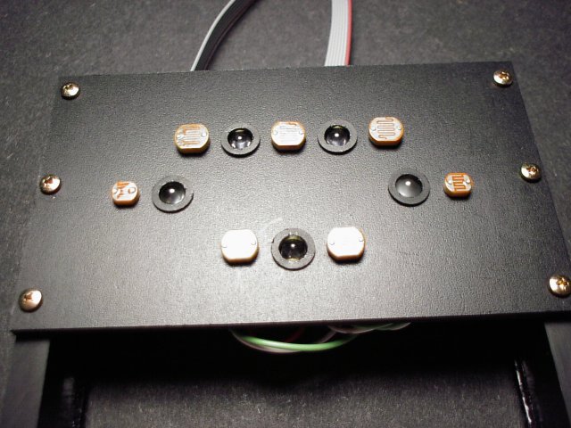
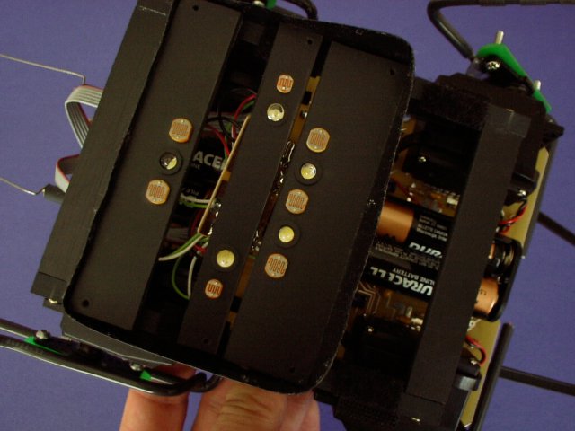
The cds schematic symbols appear in the schematics for the sensor array, and the LM324 circuit for clarity.
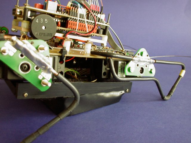
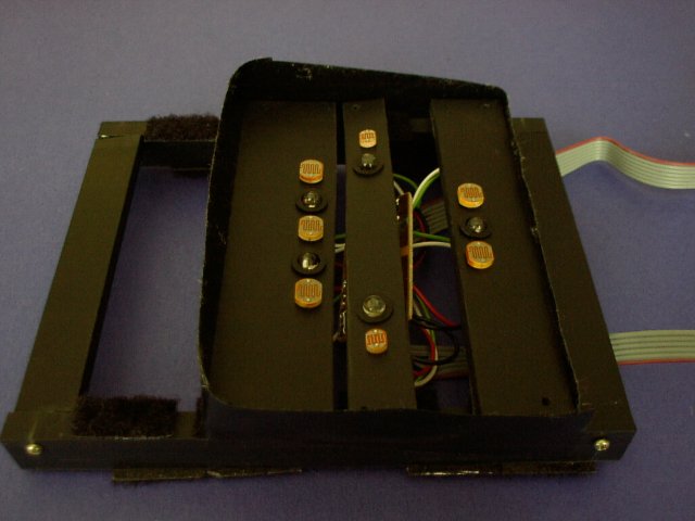
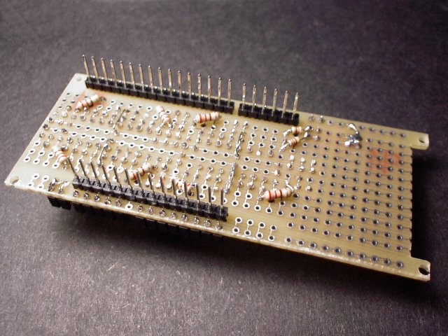
The circuit was built on a -proto-type board that inserts into the main PIC board.
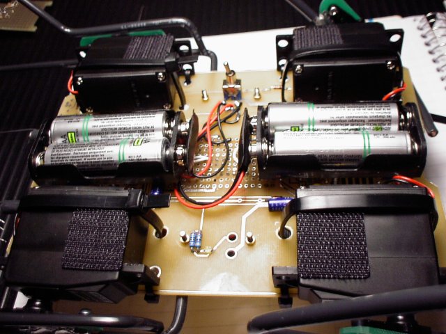
The main-PIC-board is the same width as a Solarbotics BEP Board, and the length is about
2 and 1/2 BEP Boards.
|
|
The code used at the time of the laps video was binzone5.c [ 18 Kb ], it is a state machine. Each state is a self-contained action, which asserts itself at the begining of the subroutine.
Each state(action) starts a finite loop that sync's up with the heartbeat of the master-bicore, it scans the sensor array and then using that information updates the action. If the new action is the same as the old one it continues execution of its finite loop, if the action has changed, it exits that state, and then enters the new state.
So, two possible exits from a given state. Thru normal completion of the finite loop( bot-step), or because the subroutine update_action changed it.
This project suffers from ambient light. At present there is no check or adjustments for ambient light levels. Maybe another cds cell on that unused LM324 op-amp pointed straight-up could take an ambient light level reading, and then adjust the value of black_limit before it is applied to the threshold filter.
A different sensor pattern, or use of other types of sensors would yield better results as well.
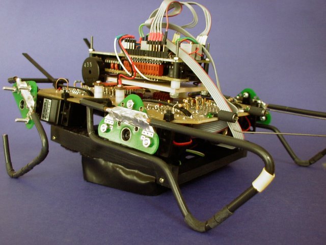
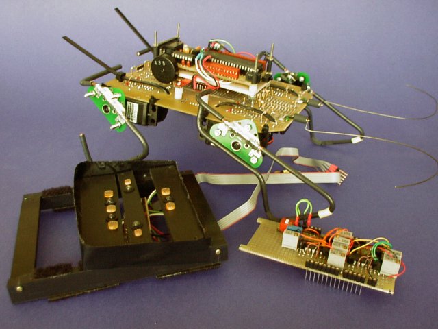
This walker is large for a line follower, a smaller version would probably fair better on a line course. Lots of room for improvement for those interested.
The video is a 8.7 MEG download, it took 10 minutes to do 3 laps around the course. Hey! ...its a walker. This AVI dosen't stream so you'll have to wait. Better viewed at Fast Forward, where the delibirate actions are easy to see.
For this project the CCS Compiler was used.
binzone5.c - Is the Line Following code.This code is supplied as is, do want you want with it.bin_cal.c - Is a program I use to calibrate the line following circuit. It prints out the converted analog values to the HyperTerminal screen via the serial connection and loops on one cds element until you are happy with the trimpot settings. The program loops continously until you turn off the PIC.