Walker Mechanical Assembly:
Circuit Board Prepartion:
First step is to solder the four clipped crimp-rings onto the circuit board. These will
be used to attach the circuit board to the Top-Plate, and need to be lined up with
the pre-drilled holes on the Top-Plate.
Among your parts, locate the clipped crimp-rings and four, #4, 1/4" screws. These screws
are actually for mounting the battery holders but we will temporarily use them for this step.
You will also notice four tooth-pics, these are NOT for your teeth, they are to be used as spacers
for this step. Fasten each crimp-ring using the 1/4" screws, into the circuit-board mounting holes.
Refer to the Drill Hole Lables
to locate the circuit board mounting holes.
Leave abit of space so you can slide the circuit board under the crimp-rings. Slide the tooth-pics
under the crimp-rings, on the other side of the screw from the circuit board. This will keep the
crimp-rings level with the circuit board for when you tighten the screws snug, to secure the
board for soldering . For now, keep them loose enough so that you can adjust the position
of the circuit board.
Near the end of the circuit board, on the rear BC2 tile,
are two large ground pads, line up the circuit
board so that the crimp-rings are on these pads. The other crimp-rings should land about the
middle of the BC1 tile along the ground rail that runs
down each side of the tile. Make sure the crimp-rings do not come into contact with any of the other pads,
if they do, then trim some off so that they don't. We don't want any shorts here.
When its all lined up, solder each crimp-ring to the board, then remove the screws to free the
circuit board from the Top-Plate.
Now that we have a way to attach the circuit board to the walker body you can put aside the
circuit board and get to work on the rest of the construction.
Connecting Body Parts:
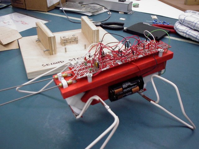
The next step is to attach the Top-Plate to the Lower-Body.
Here is a photo that shows the walker body parts
Milled from the lightest piece of spruce I could find in the wood pile.
The Top-Plate carries the circuit board and the tactile sensors.
Everything is pre-drilled , except the holes needed to attach the Top-Plate to the Lower-Body.
Line up the Top-Plate and Lower-Body so that the rear ends of each piece are flush.
Then using a 5/64" drill bit, use the holes that are counter sunk to guide the drill and drill into
the Lower-Body. Make sure your ends are flush. Once you have made one hole you can put
a #4 - 5/8" screw in so that it does not move on you when you go to drill the second hole.
DO NOT over-tighten these screws, snug is OK, if you over tighten you can strip or split
the wood.
Preparing The Motors:
Before you attach the motors to the body you need to do a few things to them.
One thing to do is add the filter caps across the motor terminals. Three on each
motor. Find the six , 0.01uF mono-caps.
Do not mix up the motors. Make sure the motors go back in the gear-box that it
came from. The gears on the motor shafts are different.
Remove the motors from the gear-box. On the front motor, (90 degree bend), use a
phillips screw driver and remove the screws. For the rear motor, un-hook the plastic
band that holds the motor into the gear-box. One side of the plastic band has been
trimmed down, and is located near the 'hook'. So, don't pry too hard or it may rip.
Solder one cap across the two motor terminals. This capacitor ends up under the
plastic-bands that hold the motors into the gear-box, make sure you leave enough
clearance to lie underneath these plastic-bands.
Take another cap and solder one of its leads to ONE of the motor terminals, then form
the OTHER lead around the curvature of the motor, solder this lead to the top-part of the
motor casing so that it remains outside the gear box once the motor is inserted back into it.
When soldering the filter capacitor leads to the side of the motor casing, Using a small
jewller file, or fine sand paper, rough up a small area that you will solder to. Remember to
keep it close to the end so that it will fit back into the gear box. Also make sure that none
of the capacitor leads that are connected to the terminals of the motor are touching the
motor casing. This will cause a short.
Now do the same to the other side of the motor with the remaining third capacitor.
Do all the same steps to the other motor as well.
Cut four wires, 2 - red, and 2 - black, that are 5 1/2" long. You don't have to use red
and black, but be consistent with your colour choices. Strip off about 3/16" off of each
end of the wires and pre-tin them by applying abit of solder to the ends of the wires.
Take one red wire and one black wire, and solder one end of each of these wires to the
motor terminals on each motor. On the other ends of these wires solder on some
machine pins and reinforce them with shrink-tubing, not to much tho..where they plug
in, there is not alot of clearance, so keep the strain relief part short.
Now you can put the motors back into the gear boxes. Here is a picture of the rear motor to give you an idea of what it should look like. Now all thats needed is to re-attach the plastic band that holds
the motor into the gear box, and you are ready for mounting.
Mounting The Motors:
Next, you are going to attach the motors, the motor with the 90 degree angled gear-box is
for the front, the straight one is for the rear. You will have to insert the wires for the front
motor thru the holes in the top-plate before you fasten it down with screws.
You could do it later...but it wouldn't be easy, if not impossible..
Use the four #4 - 1 1/4" screws to mount the motors. The front motor can only be mounted
one-way...the rear-motor is not so obvious. On the rear-motor the motor is held firmly into the
gear-box using a plastic band, that hooks over a tab on each side, on one side, the band has
been trimmed down, that side goes up against the Lower-Body. These holes are pre-drilled, but
be gentle, go slow, these are long screws going into a narrow layer of wood. The counter sink...
well it dosen't, but will not interfere with the adapter plate.
When fastening the motors to the body with the #4 screws, DO NOT tighten the screws too tight
...if you do, you will cause stress on the gear box, resulting in very poor motor travel. To Check
for this, grab the legs around either side of the motor adapter plate with one hand, use the other
hand to hold the robot. Now jog the motor back and forth. It should not give to much resistance
to this. If it still does after you have loosened the screw right off, then check to make sure that
you put the correct motor into its matching gear-box.
Mounting The Battery Holders:
Get the battery holders and mount them to the sides of the lower-body using the pre-drilled holes.
The screws to use are the four, #4, 1/4" counter sunk screws...2 for each battery holder. Mount
them with the wires towards the back of the Walker. On your two Battery Holders, you have two
red wires and two black wires. We are going to wire these up in series. What does that mean...
connect a red wire from one battery holder to the black wire on the other battery holder .
Before you solder them together, slide a piece of shrink tubing over one of the wires. When you
have finished soldering the red and black wire, slide the shrink tubing over the solder joint, and
shrink the tube by using a heat gun, or a bic lighter. You should have a red and black wire left over
that you will connect to the circuit board later on, for now solder on a machine pin on each remaining
wire and remember to slide on a small piece of shrink tubing for strain relief , keep the strain relief short
as there is almost no clearance where these connect underneath the board.
....onwards.
Preparing And Mounting The Tactile Sensors:
The tactile sensors where already built for the people attending the workshop,
but here are a two pictures that show the parts so you can build your own.
parts1 and parts2
Check the walker workshop parts list for details.
The spring wire is available from Solarbotics, the rest you can get off the shelf at
Canadian Tire, or Home Depot, or some electronics store.
You need to solder on the 'Send' and 'Return' signal wires onto the tactile sensors.
Cut four pieces of wire to 3 1/2", two of each colour. Remove some of the insulation
from both ends...approximatley 3/16", Pre-tin the ends of the wires. Solder machine
pins onto one end of each wire. Use shrink tubing for strain relief, again keep the
strain reliefs as short as possible so that they can fit under neath the board.
Now use one colour for the 'Sends' and the other colour for the 'Returns'. Take the
wires you are going to use for the 'Sends' and solder them to the side of each tube.
Take the wires for the 'Returns' and solder them to the 'ring' on the crimp-rings.
Now we can mount them on the Top-Plate. There are pre-drilled holes for this.
Fasten each tactile sensors onto the Top-Plate using #2, 1/4" machine screws
thru the crimp-ring. Then slide a 5/16" piece of shrink tubing over the brass tube.
Line this up to where you will push the white plastic cable-clamps on. Use the two,
#4, 5/8" round-head screws to fasten them down.
Building The Legs:
This section is really only applicable if you attended the workshop, as I had jigs for
bending the legs. The figures for where to mark the wire and remove the insulation will
be different for other jigs obviously.
Now we are going to prepare the adapter plates for mounting the legs onto, and we are going
to bend the legs using the #10 gauge copper wire.
Before we bend the copper wire we need to remove some of the insulation from the wire at
certain spots. Get the 44" piece, this will be the front legs. Using some kind of marker, find
the center and put a mark. Then measure 7/8" out from center on either side, and put some
marks. All measurements are from the center out, so next is 3", then 4", then 15 1/2",
then 16 1/2", and finally from 18 1/2" to the end of the wire. At this time you can snip off
2 1/2" off of each end of the front leg wire.
For the rear legs, get the piece that is 34", mark the center, then from the center out to each end,
marks at 2", and then from 14 1/2" on either side to the end of the wire.
Now we are going to remove some of the insulation, use an X-acto knife for this. Be carefull not
to slice yourself here, never cut towards your fingers that are holding the wire, just in case you
slip. For slicing around the wire, line up the X-acto knife and roll the wire. Press down just hard
enough to cut thru the insulation but not into the solid copper.
For the front legs slice around the wire at the two 7/8" marks, then slice down the wire from one
of the 7/8" marks to the other 7/8" mark. You should be able to peel off the insulation between
these two marks. Next, slice around the wire at the 3" and 4" marks, then make a slice down the
wire between the 3" and 4" marks, peel the insulation off. Next, do the same at the 15 1/2" and
16 1/2" marks. And finally from the 18 1/2" mark to the ends.
For the rear legs, remove the insulation between the 2" marks, then remove the insulation from
the 14 1/2" mark to either end of the wire. Thats it.
Once you have finished removing the insulation take you legs over to the bending jigs.
Here are a few photographs of the jigs that were used at the workshop.
Attaching The Legs To The Leg Adapter:
Now that the legs are bent into shape you need to solder them onto the leg-adapter.
I use silver solder, and an 80 watt soldering iron for this step.
The adapter board for the front legs has been trimmed down alittle on either end of the large
solder pad. On this pad is five holes. The larger diameter hole on this pad is for a mounting
screw, be carefull not to get any solder near this hole as it might make it difficult for you later
on when you mount this on the motor adapter. The other four smaller holes will be used to
insert ' U ' shaped, thin gauge copper wires to help reinforce the legs. Line up the legs and
adapter board in the soldering jig. Make sure the ends are not too close to that screw hole,
if they are then trim off alittle on the ends. Once you are happy with how it all lines up on
the pads insert the ' U ' shaped pieces into the holes, over the leg wire. Have a helper put on
some oven-mits and hold the legs in place while you solder. Make sure you use the silver solder
for the legs for a stronger solder joint. The soldering iron you are using for this step generates
much more heat than the regular soldering irons, so don't apply to much heat directly to the
leg-pads, or they will melt. Next step is to apply some solder to where you stripped off some
of the insulation, this joins the bent wire at the shoulder to help give it alittle more strength.
Although I was there to help you with this stage, there were a few who at the last minute
could not be there...so for those people.
Find a block of wood that you can lay the adapter plate flat on the surface of the block.
Make sure the piece of wood is tall enough that the legs can sit flush on the adapter plate.
When soldering the legs to the solder pad on the adapter plate, the legs should be orientated
upside down, feet pointing upwards, and the adapter plate should be orientated such that the
wire ends of the legs are on the same side of the pad where the center hole is. Also, make sure
the legs are centered, before you solder, otherwise one side of your legs will be shorter, the other
one longer, and this will effect its ability to walk in a straight line.
Attaching The Motor Adapter:
Next step is to mount the leg-pads onto the motor adapter. Use three, #2, 1/4" machine screws
for each leg-pad. Line up and insert the screws in the side holes first, do the center one last, as it
will be slightly off, and you will have an easyer time with it if you do the others first.
Now you can attach the legs to the motors, push the motor adapter on the motor shaft. Find
the small washers and two #2, 1/4" machine screws. Place the washer over the shaft and fasten the
motor adapter to the motor with the #2 screw.
Once you mount the legs on the walker you will need to adjust them so that the walker is lower
in the front end than the rear. Face the front of your walker, grab the legs just above the
adapter plate and bend the legs back, away from you towards the battery holders.
Try to achieve a low center of gravity or else it will flip over and roll when it trys to climb
and scramble over obstacles. For starters, try the front at 1" of clearance to the adapter plate
from the ground, and with 1 3/8" of clearance at the rear.
For adjusting the rear legs, bend them back from where pins 6 and 4 on the rear jig would be
using a block of wood. You can tweak it later once the electronics are done.
Now you can move onto the circuit board electronics.
Circuit Board Assembly:
You can view the circuit diagram here.
Soldering the IC's:
Before you solder in the 74AC240 on the BC1 circuit, you need to solder a jumper wire,
J5, into one of the positve pads, refer to the BC1 graphics to locate J5. This pad will be
blocked by the 74AC240 later, so we do it now. Insert the wire from the Top-Side,
solder one side of the wire to the pad that is just below the arrow in the middle of the
circuit board. Those pads running up the center connect to the positive bus on the
other side. Leave the other end of the wire disconnected for now.
Now we can solder in all the 74AC240's. There are four of them, one for each tile. Make sure
you insert them with the proper orientation, the 'notch' on the chip should match the 'notch'
on the circuit board grahics.
The Capacitors:
Find your four 22uF capacitors, one of the leads will be marked as ' - ' , the other lead is ' + ' .
When installing the 22uF capacitors, you will need to bend the leads 90 degrees so that they
lay flat up against the circuit board.
Starting with the BC1 circuit, insert one of the 22uF caps into C1 ,
make sure positive goes to positive, and negative to negative. On the
IMX circuit, insert a 22uF into C3. On the front BC2,
and rear BC2 circuits insert the 22uF caps into C3 as well.
Now find the four 0.22uF capacitors, these are mono caps and it does not matter which
way they go. On the BC2 circuits find the locations labeled C1 and C2. Solder these
capacitors at these locations.
Find the two 6.8uF tantalum capacitors, these are part of the BC1 circuit.
Find the locations of C4 using the graphics of the BC1 Tile....you won't find it screen
printed on the circuit board. Watch your polarity on this one too... + to + .
That's all for the capacitors.
The Resistors:
Let's start with R1, these are 2.2K 1/8W and are used with the LEDs. There are two R1's located
on the BC1 Tile. Use the graphics to help you locate where. Solder.
There are none on the IMX Tile so skip to the front
and rear BC2 circuits.
On these tiles ignore the fact that it says R2 and R3 and solder in two R1's in these locations. Do this for both BC2's.
There are seven 47K resistors. These are refered to as R2. Lets do the BC2 circuits first.
On the circuit board look for the screen printed R1 next to a capital 'E' . You got it..solder in R2 at R1.
Do that for both front and rear BC2's.
Next on the IMX board locate the screen printed R5 and R6, put two R2's there.
For the next two refer to the graphics for the IMX.
One R2 goes from the pin 1 of the IC(leftside-component view) to a pad next to MUX1.
The other R2 goes from pin 19 of the IC(rightside-component view), to the ground pad at the corner of the board.
OK..so why is there one R2 left...if you are planning to use external control of the NU's enable...thats on the
BC1 circuit, then you will need to cut a trace and add the 47K resistor.
Otherwise no need to cut the trace, as the default for the enable is low(ground).
Next is R8, they are 100 Ohm resistors for the power/charging circuit. If you decide to install a
charging jack later, you can charge up Ni-Cads, the LED will go out when its fully charged.
Anyways...They go where?..you guessed it at locations R1 and R2 on the circuit board.
Referring to the BC1 graphics locate the two R4's, this is where
the two 1.5 Megaohm resistors
go that work with the 6.8uF caps to set up an RC time for the tactilet sensors. To solder these in,
take one of the leads and bend it right around and parallel with the other lead, like a thin ' U ' shape.
Insert and solder.
You still have a few resistors left over. Save those for a step later on .
Diodes And LEDs:
Do the diodes first. On the IMX graphics locate where
two D1's are at the top of the circuit.
On the IMX circuit board, resistors would normaly go where we are placing these diodes.
That translates to the circuit board as ... R1 and R2... notice a pattern here? Anyways...the
orientation of the diodes are important. The vertical line off the tip of the triangle in the
graphics, corresponds to the black ring on one side of the 1N914 diode. Make sure they
have that orientation, and are inserted from the bottom and soldered from the top.
ALL LEDs ARE INSERTED FROM THE SOLDER SIDE(TOP) AND SOLDERED COMPONENT
SIDE(BOTTOM). There are seven tiny LEDs. Four red ones, two green ones, and one yellow.
Lets eat the red ones first.... I mean lets do the red ones first.
On the front and rear
BC2 tiles you will find two small lables screen printed near the bottom of each
board, L1 and L2. Notice the triangle thingy with that vertical line... just like a diode...
the orientation is important. On those tiny LEDs, if you look closely, one of the sides
where the leads come out has a silver or gold mark on the flat part of the plastic lens.
This will help you to match the orientation to the circuit board. Make sure you do that
for each LED. Try not to be on too long when soldering these, I have seen people melt
them.
OK, so insert the red ones into the top of the BC2s, one at a time, and solder them in.
Now the yellow one. On the chg 1.0 circuit, locate the diode
symbol with the emitter arrow, insert it from the top, and solder from the bottom.
The green ones were left for last because they are the trickest. Refer to the
BC1 graphics and locate L1 and L2.
Before you can solder these in you need to make two small jumpers and solder them in first.
J1 and J2 on the BC1 graphics. Cut two pieces of wire, 1" long, or longer if thats too small
for you to work with. Strip off some insulation from either end, and pre-tin them.
Insert from component side(bottom), solder from the slder side(top).
Jumpers J1 and J2 are very hard to see on the BC1 graphics. If you look closely at the
positive trace that goes down the center of the tile, you will notice J1 in between the
lables R1, in white, hiding in the grey colour of the trace. J2 is just below that, in white.
Sorry, poor choice of colours, for that one. This has been fixed for the next print.
Now you can solder the green LEDs in. Refer again to the graphics for the BC1.
Trim the leads down to a length of 1/8" (3mm). This lies on top of pads where you
have already soldered a resistor lead and a jumper lead. If you don't have some
method of holding it there while you solder, get someone to hold it for you using
tweezers. Once you have one side tacked (soldered). Your helper can let go.
Make sure the orientation is correct.
The Switch:
On the Chg 1.0 circuit board locate the graphics for the
switch. Insert from the bottom, and
solder from the top. The placement of the switch on the bottom side is to help protect it.
Turning it on/off might be tight for you, but accessible. If you feel that you would prefer
to mount the switch on the top or side go ahead...it's only a switch!
Machine Pins:
You are going to put machine pins on the bottom side of the BC2's for the motor
connections. Locate the rectangular screen print on the front and
rear BC2 circuits that
is labled O1 and O2 . After you have located the lables O1 and O2 on the BC2
circuits, solder a machine pin in each of these locations.
On the BC1 circuit you need to put in four machine pins for the 'Send' and 'Return' of
the right and left tactile sensors. Refer to the BC1 graphics to locate where to solder
these pins.
On the Chg 1.0 circuit solder two machine pins at batt+ and ( - ) common ground.
This is where the batteries will connect to. Insert from bottom, solder from top.
Next you need to solder in six machine pins. Insert from bottom, solder from top .
Later on we will insert some resistors into these locations. These resistors affect the
durations of the bicore pulses. More on that later.
On the Front BC2 board, locate R4, solder in a pin on either side of that, this is where
the resistor we refer to as R6 will go.
On the Rear BC2 locate the square boxes labled I1 and I2, solder one machine pin in
each of these. To locate where the other two machine pins go, refer to the Rear BC2
graphics. Find where the R5's go. Solder in the pins at these locations.
You should have four machine pins left over. You are going to make two special jumpers.
Cut two pieces of wire 3 1/2" long. Then cut these in half again. Strip off some of the
insulation from either end. Pre-tin the ends of the wire. Solder one end of each wire to
the ' pin ' of a machine pin, ( the pointy end ). Cover the solder joint and machine pin
with shrink-tubing, but leave the very end open so we can insert a resistor in later on.
Once you have all four ready. We can solder them in. Two of them are soldered into the
Rear BC2 circuit at locations I1 and I2. Refer to the Rear BC2 graphics, look for the
' To IMX R7 '.
The other two are soldered into the IMX circuit,
and are jumpers labled R7 with an arrow to
'To Rear BC2 Input' on the graphics. The Front-n-Back graphics
refer to this jumper as well. Later we will connect the jumpers together using resistors R7.
The Jumpers:
Its jumper time.
Referring to the graphics. Start with the BC1 circuit. Jumper J3 thru J8 are
inserted from the solder side(top) and soldered on the component side(bottom).
Jumpers J9 and J10 are inserted from the component side(bottom) and soldered
from the solder side(top).
For the IMX circuit, J20 is inserted from the solder side and soldered from the
component side. The other end of J9 and J10 are inserted from the component
side and soldered from the solder side. Jumpers J11 thru J19 are also inserted
from the component side and soldered from the solder side.
For the front BC2 circuit J16 and J17 are inserted bottom side and soldered top side.
For the rear BC2 circuit J18 and J19 are inserted bottom side and soldered top side.
If your board was stitched together, you only need to put the positive jumpers, J+ ,
where the breaks between the boards occur, the process of stitching the boards
together connects the grounds for you. If your board was all one piece, grounds
and positive are all connected except the positive that comes from the Chg 1.0 circuit
to the rear BC2, which is labled J21 on the graphics for the Chg 1.0 circuit
Finishing The Walker Assembly:
You still have some resistors to insert into machine pins, but for now you are finished
soldering. Go give you board a good wash with soap, water, and a tooth brush. Then
pat them dry with a paper towel. Water will get trapped underneath some of the
components. Blowing on it will get rid of some of the water that is trapped. After that
get a hair-dryer and dry it some more until it looks fairly dry.
Now you can finish the assembly of your walker.
Find your 2.2 Meg resistor ( red, red, green ) bend the leads 90 degrees, then snip them
off leaving about 1/4" of lead left. Insert this into the machine pins on the front BC2
at R6.
Find the two 1 Meg resistors, ( brown, black, green). Do the same, bend the leads over
90 degrees and trim the leads down to 1/4". Insert them into the rear BC2
at locations R5.
Find the two 3.3 Meg resistors, ( orange, orange, green ). Keep the leads straight but trim
the leads down to 1/4" . Insert each of these into the R7 jumpers that you have wired in.
This will connect from the IMX to rear BC2. Refer to the Full View
to help you locate the R7 jumpers
Now all thats needed is to connect the tactile sensors, motors, and power, up to the
circuit board.
To connect the tactile sensors refer to the BC1 circuit graphics.
The front motors connect to the front BC2 where you soldered the machine pins in
at O1 and O2. The rear motor connects to the rear BC2 at O1 and O2. If you where
consistent with your colour coding when you wired up the motor, then just make sure
that the wires to the rear BC2 are opposite to that of the front motor.
The only thing left to do is plug in the battery holder...red to batt+, black to common ground.
Remember the machine pins you soldered onto the Chg 1.0 circuit.
OK, all plugged in? Now, using the four #4, 3/4", round heads and
3/8" nylon spacers attach the circuit board to the Top-Plate. Snug is good...not to tight.
Now are you sure it's completely dry? If so, install your AA batteries and turn it on.
Does it work? If not, make sure you have not missed any steps...if it still does not work
come and get me to look at it.
It works, but it goes into a reverse turn, or full reverse, all by it's self?
If you are experiencing false triggering from the tactile sensors there are a couple of ways
to deal with it.
You should have had two - 4.7K resistors left over, desolder the return wire from the tactile
sensor crimp-ring, trim down the resistor leads, to about 3/16" solder one side to the crimp-ring,
slide a piece of shrink-tubing over the tatcile return wire and then solder it to the other side of
the resistor. Apply heat to the shrink tubing. Then plug it back in.
If it still false triggers, then see if you can add another small piece of shrink tubing to the sensor
spring inside the brass tube, make sure the wire can make contact with the edge of the tube, else
it will not work.
Another thing is to nibble off small lengths of the tactile spring from the ends. Its amazing how
1/2" can make the difference. For example, my walker's tactile length, from the end(front) of the
brass tube to the tip of the spring is 4 5/8", it use to be 5", until I trimmed off 3/8" from the ends.
This got rid of the false triggering for me. Don't trim off too much. The tactile spring should still
outreach the farthest forward position of your front legs.
If it still false triggers contact me and we will see what can be done to help you.
You will also have to ' tweak ' the legs alittle. Proper balance and leg shape is important.
I will do a quick tutorial on that at the workshop. If you are not at the workshop I would
recommend refering to pages 310 - 316 , of Dave Hrynkiw's book, Junkbots, Bugbots &
Bots On Wheels. You can also look at the Leg Grid Diagram,
this is the system I use, and
is slightly different from Dave's system. It shows distance ratios between the Front and Back Legs
in relation to the Center Of Gravity of the Walker. The Large dots in the diagram are where the 'feet' touch the ground.
Use what method appeals to you. Also, be aware that the legs use the body of the walker for its leg limits. If the
motors are making a rachetting sound, (thats the slip clutch), then adjust the legs so that they are not slamming up
against the body...or use less voltage. Using 1.2v Ni-Cads are perfect for this type of Robot.