|
|
|
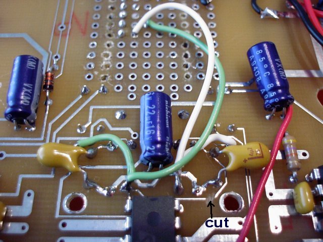
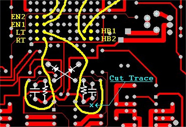
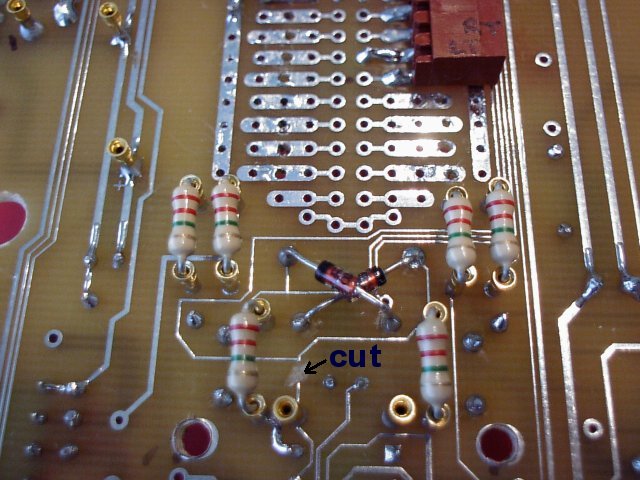
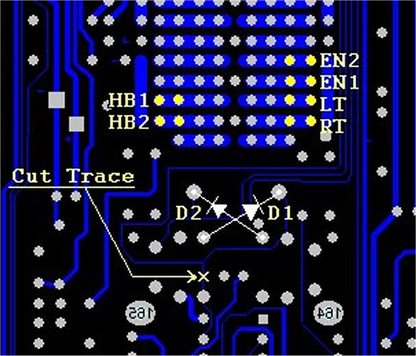
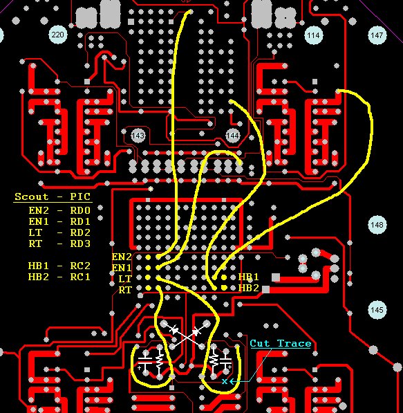
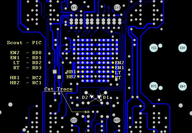
1. We need to cut two traces on the Scout II Walker circuit board. Please refer to
     the images and photos to locate the traces. There is one trace top-side of the
     board, and one trace on the bottom-side(motor-side).
|
|
|
|
2. Insert and solder Diodes D1 and D2. These Diodes prevent the PIC from charging up
     the RC for the Tactile Sensors when the PIC processor takes control of the IMX, but
     still allows for normal operation of the IMX and Tactile Sensors.
|
|
|
|
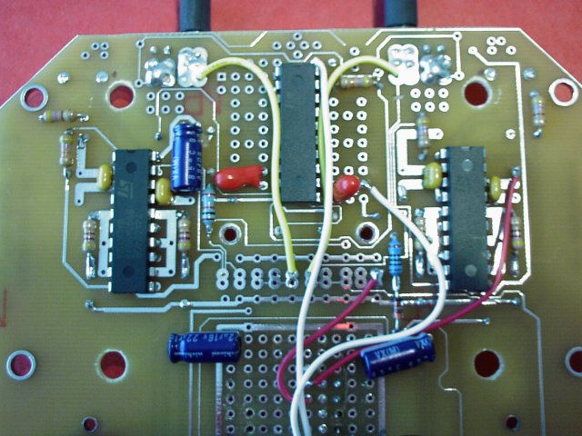
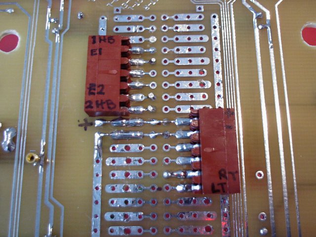
3. In the center of the Scout II is a breadboard area. This is where we are going to
     bring all the jumper wires to the break-out (molex Connectors). In this particular
     case we are only using 6 connections from the Scout to the PIC. If you have not done
     the 'Sunseeker Head Modification' you only need 4 connections, and can ignore any
     references to HB2 and EN2. I used right-angled female molex connectors to keep a low
     profile since the main PIC board is directly above them. So,...have you soldered in the
     molex connectors yet?...good...next.

4. You are going to need 6(4) jumper wires to connect the signals we are interested in
     to the Molex breakout. These signals are: HB1, the HeartBeat of the master bicore.
     HB2, HeartBeat of Sunseeker/walk cycle. EN1, Enable for all motor bicores. EN2, Enable
     for Sunseeker/Walk bicore,  RT and LT are used to monitor the tactile sensors, and to
     take control of the IMX.
|
|
|
      Refer to the pictures to help you locate the pads of interest. In the photographs the
      molex-connectors are in a different location, and the order the jumpers terminate at
      the molex is different as well. Just follow the circuit board diagrams instead of the
      photos, you will end up with a cleaner interface to connect the breakout to the main
      PIC board.
|
|
|
|
   Thats all the soldering for the Scout II board...make sure you clean up any flux left
   on the pads and traces.
|
|
|
5. Next, build some cables that will connect the molex-breakout on the Scout II, to the molex
    connectors on the main PIC board.
|
|
|
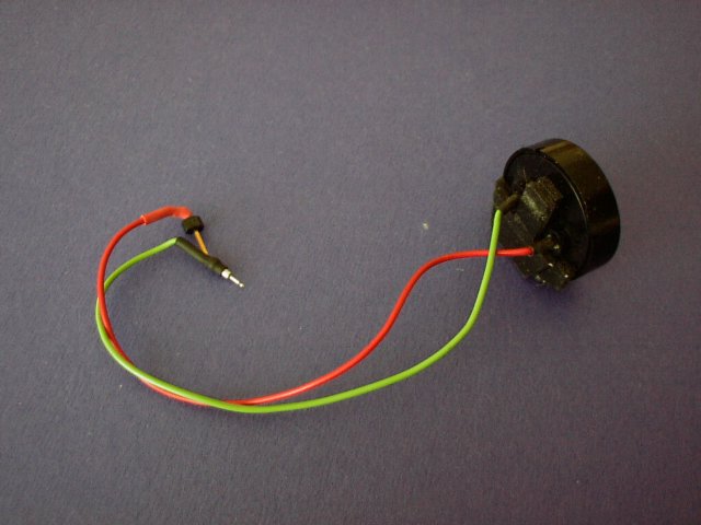
6. Now might be a good time to garb a piezo speaker and solder some jumper wires on
     the leads, use shrink tubing on both ends of wire, for strain releaf.
|
|
|
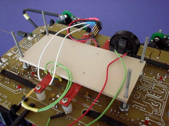
7. Construct the platform the main PIC board will sit on. You can make an adapter plate,
easily from Sintra and use the same leg-mounts used in the SunSeeker Head Kit. Or
make your own. You will need to drill some holes in the four corners to mount the
circuit boards and four holes in the center to attach the leg-mounts to the adapter
plate.
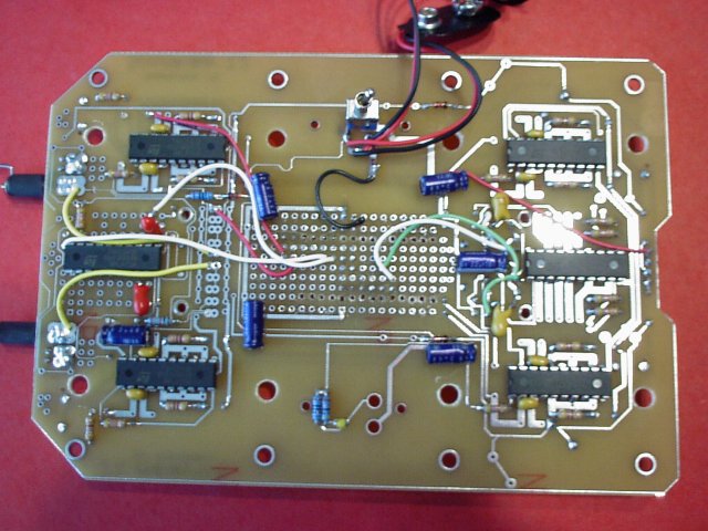
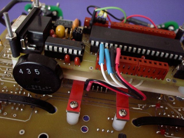
8. Take the connector cables you built to interface the Scout to the main PIC board
and plug in the cables to the molex on the Scout. Mount the adapter plate on your
Scout II, same place where the SunSeeker Head would go. Use some double-sided sticky
tape and mount the piezo speaker as shown in the photo.
|
|
|
|
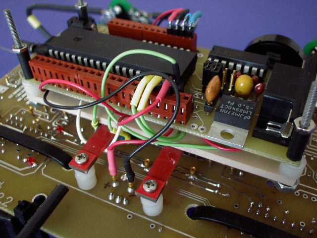
  9.  Mount the main PIC board, using posts and threaded rod.

10. Connect the interface cables to the PIC board, V+INB,GNDB, and the piezo-speaker.
       That's it.

11. Once you have a bootloader program flashed onto the PIC, you can download your own
       programs into the main PIC board using a serial port and a straight-thru serial cable
       with DB9 connectors.
|