Photovore Workshop Tutorial
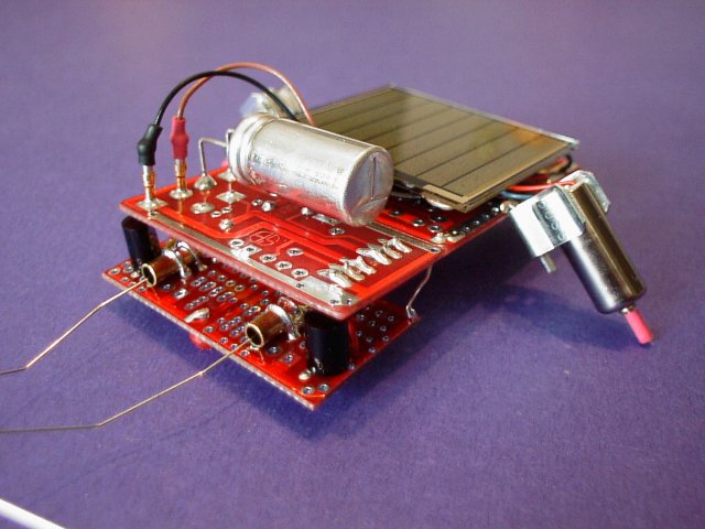
This is a picture of the proto-type that was built before the workshop. It has brass tubes and #12 guitar strings for its sensors, otherwise everything else is the same.
This is a picture of the proto-type that was built before the workshop. It has brass tubes and #12 guitar strings for its sensors, otherwise everything else is the same.
|
Building the Miller Engine: All soldering is from the solder side (top) of the circuit board. 1 - Refering to the component side(Bottom View), insert the diode into the place labled D1. Make sure you note the orientation of the diode. Then solder it from the top-side. Clip off the leads and SAVE them for later use in this project to connect the sensor board to the main board. 2 - Find the 1uF capacitor and insert it into 'C2'. Solder. 3 - Find the ZVN2106 Fet and insert into 'transistor'. Note orientation. Try to get the 2106 Fet as close to the circuit board as possible. We need a low-profile. Solder. 4 - Take the 1381-J trigger and insert into '1381' . Note orientation. Keep a low-profile, like the 2106 Fet. Solder. 5 - Make two short jumper wires(J9, J10) about 3/4" long. Connect the positive and negative rails from the Miller Engine tile to the BC1 tile. Solder. For steps 6, and 7, the components are mounted on the solder side(top), (opposite side to the previous steps). 5 - Refering to the Solder side(Top View), insert the two machine-pins for the solar cell from the solder-side. You might want to insert, and solder, each one seperately. These are soldered from the solder side too. 7 - Find the 3300uF capacitor. Bend the leads down 90 degrees, about 5/16" from the capacitor can, insert into C1. Check the orientation by referring to the top-view. I like to strip off the plastic sheath from the capacitor can...just for looks...make sure you remember to take note which lead is positive and negative. Also if you do this...make sure the can is not touching any solder pads. SAVE the leads after you clip them to use in the construction of the tactile sensors. 8 - Thats it for the Miller Engine.
Building the Tactile Sensors: Basically you are about to make a sensitive switch. The spring wire is insulated from the machine-pin by some shrink-tubing. When the robot bumps up against something the spring will make contact with the machine-pin and the signal will flow to help pre-bias the bicore. For now take a deep breath and.... 1 - Solder a piece of clipped lead into the end of each long machine-pin. You can use a piece you clipped from the 3300uF capacitor. 2 - Cut 2 pieces of shrink-tubing to 1/4" lengths. 3 - Slide shrink-tube over the machine pin to the end, where the wire was soldered to. Apply heat. 4 - Next, slide the spring part of the tactile sensor over the machine-pin, and onto the shrink-tubing, you WILL have to carefully stretch the spring alittle...just go slowly, you don't want to over-stretch it. Make sure that the machine-pin does not touch any part of the spring. If it does your tactile sensor(switch) will always be 'on', which we don't want. The tactile sensor is a sensitive, normaly-open, momentary switch. 5 - Once you have worked the spring part over the shrink-tubing, bend the 'short' lead of the spring towards the hole that you will be soldering to for the 'return'- signal from the tactile sensor. The 'send' - signal is the wire that you soldered into the machine pin, bend it 90 degrees and insert it into the positive rail '+', from the top of the BB1 tiles. 6 - Solder the 'send' machine pin first, then bend the 'return' wire to reach the 'return-signal' pad, and solder that. 7 - Clip off any leads sticking thru the holes. Done.
2 - Insert the pin from the component side into the second 'ground' pad in the center of the tile. Solder it, and then clip off the extra lead, note, don't use your regular wire-snips to cut this lead, find a stronger pair of cutters for this. Done.
Wiring the Photodiodes, and Jumper Wires: 1 - Insert the photodiodes into the solder side(top) of the BB1's, and solder from the component side(bottom). 2 - We have to make some jumper wires(J1-J6) to connect to the input of the bicore. I would recommend using some kind of color code that makes sense to you. You will need 4 pieces of wire that are 2" long, two of each colour. You will also need 2 pieces, the same colour, one 1 3/4" long, and one 1" long, and 2 more pieces that are 3/4" long. If these are too tiny for you to work with, make them alittle longer. Prepare some mouse-wire by stripping off the insulation and pre-tinning both ends of the wire. Stripping off about 3/16" of each end is plenty. You can snip them down to size later. 3 - Referring to the component side(Bottom View), using the 2" long pieces, and following some kind of color code, insert the wires(J1-J4) from the solder side(top) of the BB1. Bend the leads over so that they reach the pads of the photodiode. You might need to snip them down to size here. The pads are pretty close together, so be carefull when soldering these. You should end up with two different coloured wires coming from each photodiode. Dont connect the other end of the wires yet...thats later. 4 - We need to add some wires that bring the positive signal to the BB1. First, take the wire(J5) that is 1" long and connect the two positive rails on each BB1. Then take the wire(J6) thats 1 3/4" and solder it to ONE of the positive rail pads. Leave the other end un-connected for now. 5 - Next we need to connect the returns of the tactile sensors to one side of each photodiode. Use the two 3/4" pieces (J7 and J8). I would recommend soldering one side of the wire to the tactile-return-pad first, then solder the other side to the photodiode pad. 6 - Thats it! I would also take the time to lightly scrub the solder joints with a tooth brush, using soap and warm water to remove the flux from the Hydro-X solder we are using. Then put it aside to dry while you build the rest of the boards.
The Solar Cell: 1 - Cut two different coloured pieces of wire to 2". 2 - Using wire-strippers, strip off about 3/16" off each end of the wires. Give the ends a twist with your fingers to re-braid the wires. Then pre-tin these ends with solder. 3 - Insert one of the ends into a machine pin and solder. Take a small piece of shrink tubing and slide it over half the machine-pin and the wire. Apply heat to shrink the tube. Presto...wire strain relief. Now do the other wire. 4 - Now we are going to attach these wires to the '+' and '-' solder pads on the solar cell. What I like to do is tape the solar cell, face down, on a block of wood or tile, (something that can take alittle heat), (plastic is not a good choice!), using masking tape. Take the wires and bend the ends 90 degrees, use pieces of masking tape to hold the wires in place so you can line up the + and - solder pads on the solar cell with the wires. Place your soldering-iron tip onto the wire and pad, and apply abit of solder.The flux in the solder will help heat the solder area faster. Don't apply heat for too long, its possible to burn off the solder and then nothing will stick to it. Or, you may crack the solar cell from too much heat. 5 - Thats it for the solar cell. Put it aside in a safe place, where it won't get crushed by some dropped tool.
The Motors: 1 - Cut two pieces of shrink tubing 3/16" long. Place one of the pieces over a motor axil and apply some heat to shrink the tube until it 'grips' the shaft...like a low-profile tire. Do the other one too. 2 - This step can wait until the you actually go to mount the motors, and wire the motor leads to the circuit but, if you like... You can also use some wire strippers and strip off alittle more insulation on the motor wires...use the 28 guage setting, and be gentle. It is possible to pull the wires right out if you are too aggressive a stripper. Make sure you leave enough motor lead to reach the circuit pads. Refer to the Top View diagram for the locations 3 - Thats it for prep work...put the motors aside and go onto the next step.
All soldering is from the Solder side (top) of the circuit board. 1 - Referring to the component side(Bottom View), insert the 74AC240 IC into the pads. Make sure its not in backwards! Check to make sure the notch on the chip matches the graphics on the circuit board. Flip over and solder the pins solder-side. 2 - The orientation of the fuse clips are important to note. Refer to theSolder side(Top View) . On the fuse clips, look for the stop tabs on one end of each fuse clip. These are 'our' motor backstops. Make sure they are toward the circuit board when you solder. The fuse clips have two outer tabs bent at 90 degrees, the outer-tab opposite the motor backstop can be straightened out flat if you like. You can clip it off later if you want. Bend the outer tab that is on the same side as the motor back-stop to approximatly 45 degrees. Do the same to the other fuse clip too...don't forget about the back-stop tab. You are now ready to mount these onto the BC1 circuit board. Your are going to solder these bent tabs to the negative rails on either side of the BC1, check the Top View for the location. Try not to solder the fuse clip itself, just the bent outer tab, to make it easy to adjust the motor angle later on. Now, referring to the component side(Bottom View). 3 - Find the two 0.22uF caps and solder them in at C4 and C5. 4 - Insert the 1uF cap into C3...polarity counts on this one, mind your orientation. 5 - Now we have to solder some jumpers point to point. J11 is the only jumper inserted from the top and soldered on the bottom. All other jumpers(J12 -J23) are inserted from the bottom and soldered on the top. Refer to the component side(Bottom View) for where all these jumpers go. It would have been to crowded to lable J14 thru J23 so just follow the colour code...green and light-blue. 6 - Next is the trim-pot. Before you insert the 100K trim-pot into its location, use a DVM to measure the resistance on each side and adjust the values until they are equal(approximate). Then insert into location and solder. 7 - Now its time to connect J1 thru J4, and J6 from the BB1's to the BC1. Refer to the component side(Bottom View), for location. 8 - Before the next few steps you need to go wash your boards with soap, warm water, and a tooth brush to remove the flux. Dab them dry and use a hair-dryer, or let them sit under a desk lamp for awhile until dry. 9 - Now take the lead-clippings from the diodes(you did save them...right?) and use them to attach the BB1 board under-neath the Miller engine. Refer to the solder side(Top View). Look for Wire Lead connect (1)-(2) , and (3)-(4). Solder the wire into each side of the BB1's first. Then connect the BB1's to the BC1. You want as low a profile as possible , the photodiodes should be up against the bottom-front corners of the Miller Engine, the wire that connects points (1)-(2) and (3)-(4) should be at an angle, making the BB1's slightly tilted towards the back. 10 - All that is left to do is to strip off alittle more insulation from the wires coming from the motor...be carfull with these wires, if you pull on them too hard you can pull them right out. Pop them into the fuse clips and then locate the holes to insert them, refer to theSolder side(Top View) for proper location and colour code. You are going to solder from the component side. The motor pads on the left-side of the circuit board are easy enough,...but, the right side is tricky because of the trim-pot which partially obscures the motor pad. Just be careful, and don't have your soldering-iron on it for too long. 11 - Get the solar cell you attached the wires and machine-pins to, apply two layers off double-sided sticky tape(1" long) to the under-side of the solar cell, try to center it as best as you can. Then line-up the solar cell to the middle of the BC1 tile and press down firmly. Plug in the machine-pins, + to +, - to - . Then go put your photovore under some light. If all went well it should start to work within seconds.
|